What a Design for Manufacturing Review Catches Before Tooling
Design for manufacturing (DFM) means shaping a part so the process you picked can make it the same way every time at the cost you planned, and a DFM review is the check of your CAD that the factory or toolmaker runs before any steel is cut. It flags missing draft, walls that are too thick or uneven, undercuts that need moving parts in the mold, tolerances tighter than the process can hold, parts that could be merged, and finishes that change the geometry, while each fix is still a CAD edit instead of a mold modification.
This guide is for US product brands with a working prototype and a factory quote, about to pay for tooling in China, Vietnam or Mexico. It covers what a DFM review checks, what a factory DFM report looks like and how to answer it, and what a change costs once the mold exists. For the molding process and mold costs, start with our guide to plastic injection molding.
Where a DFM review fits before tooling
A DFM review sits between the last prototype and the tooling order. Prototypes rarely test moldability. A 3D printed or machined prototype needs no draft, has no parting line and is never ejected from a mold, so a shape that prints well can still be impossible to mold as drawn. Our guide to rapid prototyping methods covers how to reach a design worth reviewing.
Factories often run the review in two rounds. A first pass comes with or soon after the quote and checks draft, the parting line, wall thickness and whether your tolerances are feasible. A full report follows the tooling order and adds the gate location, the ejector pin layout, side actions and cooling, plus mold flow results. The appliance maker BSH builds its supplier DFM template on that split, with each item marked as needed for the quotation or after the tool order, and an OK or NOK box on every page for the buyer to sign and date. The manufacturing platform Fictiv works the same way: its final report needs the buyer's written approval of the parting line, ejection layout and gate location before it starts making parts.
The timing matters because a fix that is a new CAD revision before the tooling order becomes work on the mold afterward, and some changes cannot be made to the existing mold at all. The last section of this guide shows which.
What a DFM review checks on a molded part
Start with draft. Draft is a slight taper on every face that runs parallel to the direction the mold opens, so the part slides off the core instead of dragging along it. The published design guidelines from Protolabs call for at least 0.5 degrees on vertical faces and 2 degrees in most situations, with more on textured faces: at least 3 degrees for a light bead blast finish (PM-T1) and 5 degrees for a medium one (PM-T2).
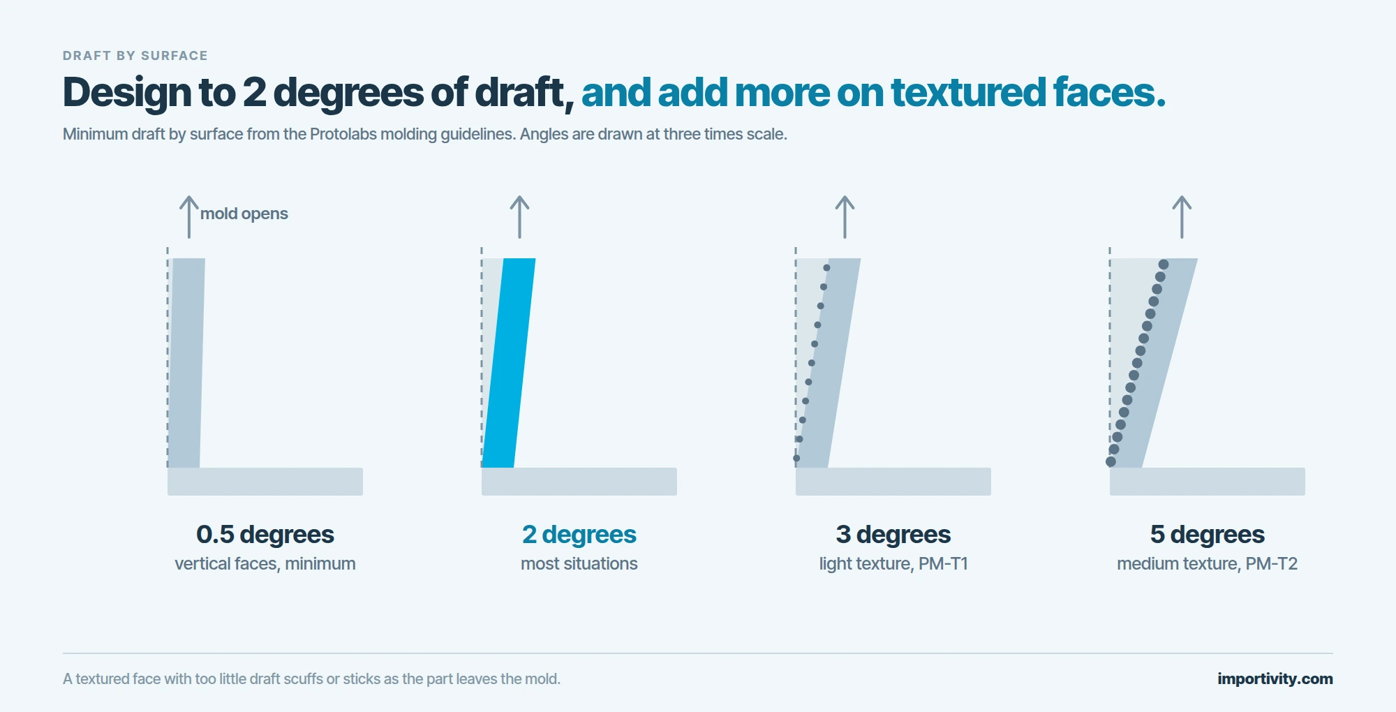
That last point is easy to miss. A texture is part of the geometry, so a face drawn with 1 degree of draft and given a textured finish will scuff or stick when the part comes out. Decide the finish of every face before the review, not after the first samples. The rest of the review works through the part feature by feature:
- Wall thickness. Each resin has a range it molds well in. Protolabs lists ABS at 0.045 to 0.140 inch, polycarbonate at 0.040 to 0.150 inch, polypropylene at 0.035 to 0.150 inch and nylon at 0.030 to 0.115 inch. Walls should also stay close to uniform, with no wall less than 40 to 60 percent of the thickness of the wall next to it. Thick sections cool more slowly than thin ones, which leads to sink marks, voids and warp.
- Ribs and bosses. A rib as thick as the wall it stands on leaves a sink mark on the outside face behind it. A common guideline is a rib about 60 percent of the wall. Heavy bosses get cored out for the same reason.
- Undercuts. Any feature that stops the part coming straight off the core, such as a snap hook, a side hole or a lip, needs a side action, a lifter or a hand-loaded pickout, or a design change. Each one is a moving part in the mold that adds cost and upkeep.
- Gate location. Where the plastic enters decides how the part fills, where weld lines form and where the gate mark sits. The factory proposes it, and you confirm it is off your cosmetic faces.
- Ejector pins. Pins push the part off the core and leave small round marks. Their layout should avoid any surface a customer sees.
- Parting line. Where the two mold halves meet leaves a fine line on the part and decides which way each face needs its draft.
Tolerances, material and finish callouts
The second half of a DFM report reads your 2D drawing, and the question on tolerances is whether the process can hold what the drawing asks for. Protolabs quotes molded parts at plus or minus 0.003 inch on the mold plus a resin tolerance of at least plus or minus 0.002 inch per inch, and machined parts at plus or minus 0.005 inch. A drawing with a tight tolerance on every dimension pushes the factory toward a slower process or a no quote. Put tight tolerances on the features that mate with another part and leave the rest at the shop's standard. Our guide to sourcing CNC machined parts shows what a blanket tolerance does to a machining quote.
Material and finish belong on the drawing as exact callouts. Name the resin grade, not just the family, because the toolmaker sizes the cavity for that resin's shrink rate, and a different grade after the steel is cut can move every dimension. Name the finish for each face, because a textured face needs more draft than a polished one, and a cosmetic face needs the gate and the ejector pins kept off it. If the factory proposes a local equivalent resin, ask for its data sheet and approve it in writing before the review closes.
Fewer parts, fewer molds
Every separate molded part needs its own mold, its own first article check and its own line on the inspection report, and every joint between two parts is an assembly step and a place for a fit problem. Design for assembly, the other half of DFM, asks whether each part needs to exist at all. The test published by Boothroyd Dewhurst, the firm behind the DFMA method, keeps a part separate only if it meets one of three conditions:
- It moves. The part moves relative to the parts around it in normal use.
- It must be a different material. A seal, a spring or a conductor that the neighboring part cannot be made of.
- It must come apart. It has to be separate so that parts meeting the first two tests can be assembled or removed.
A part that meets none of the three is a candidate to merge into its neighbor. Two housing halves held by six screws can sometimes be held by molded snap fits instead, which removes the screws and the time to drive them but adds undercuts to the mold. The DFM review should price that trade, and a bill of materials with every part listed is where the count starts.
Machined and sheet metal parts get a DFM review too
Parts made without a mold still get reviewed, and the checks change with the process. On a CNC milled part, inside corners come out rounded to the radius of the cutter, so a sharp inside corner on the drawing is a flag. Protolabs limits milled depth to 2 inches from either side of a part, recommends features thicker than 0.020 inch, and holds a standard machining tolerance of plus or minus 0.005 inch.
On sheet metal, the whole part has to keep one wall thickness because it is cut from a single sheet, and Protolabs works from 0.024 to 0.250 inch. Holes and tabs within about 4 times the material thickness of a bend can distort when the bend is formed. Flanges need to be at least 4 times the material thickness long, and Protolabs recommends using the same bend radius on every bend of the part. More cost rules for bent parts are in our guide to sheet metal fabrication.
What a factory DFM report looks like and how to answer it
A factory DFM report is usually a slide deck with one issue per page, built on screenshots of your CAD. Expect color maps for draft and wall thickness that mark failing faces in red, then the proposed parting line, the gate location, the slider and lifter positions with their direction of travel, the ejector pin layout, venting and cooling, and a page of suggested changes. A full report adds mold flow results: fill time, pressure drop, weld lines, air traps, sink marks and warp.
Read it as a set of proposals that you either accept or reject. Protolabs splits its automated feedback into required changes, which must be fixed before a mold is milled, and advisories, which you may decline. Large buyers also write down what the factory's silence means. The BSH template states that if the supplier raises no remarks on the buyer's requirements, the supplier is taken to confirm it can meet the specifications for the product, the tool and the process. Put the same sentence in your own tooling terms, so a problem the factory never flagged stays the factory's problem. Then answer the report page by page:
- Check that the CAD file name and revision on the report match the latest one you sent
- Answer every page in writing: accept, reject, or accept with a change
- Separate required changes from suggestions, and ask for the reason behind any required change you do not understand
- Mark your cosmetic faces before the factory places gates and ejector pins
- Confirm the parting line, gate location and ejector layout in writing before any steel is cut
- Ask which resin grade and shrink rate the cavity is being sized for
- Ask for mold flow results on large parts, thin walls or cosmetic faces
- Send revised CAD under a new revision letter and get a final report on that revision before you approve the tooling
- File the signed report with your tooling and mold ownership agreement
When the first shots come off the tool, a first article inspection measures the part against the revision you approved here.
What a change costs once the steel is cut
Every change after the review comes down to one question: does the mold lose steel or gain it. Cutting more steel out of a cavity makes the part bigger or thicker, and a toolmaker can usually machine that into the existing mold. Putting steel back makes the part smaller or thinner. Protolabs, writing about its own mold modifications, says it can add plastic to a part but never take it away. On a production steel mold, taking plastic away means welding new metal into the cavity, replacing an insert, or cutting a new mold.
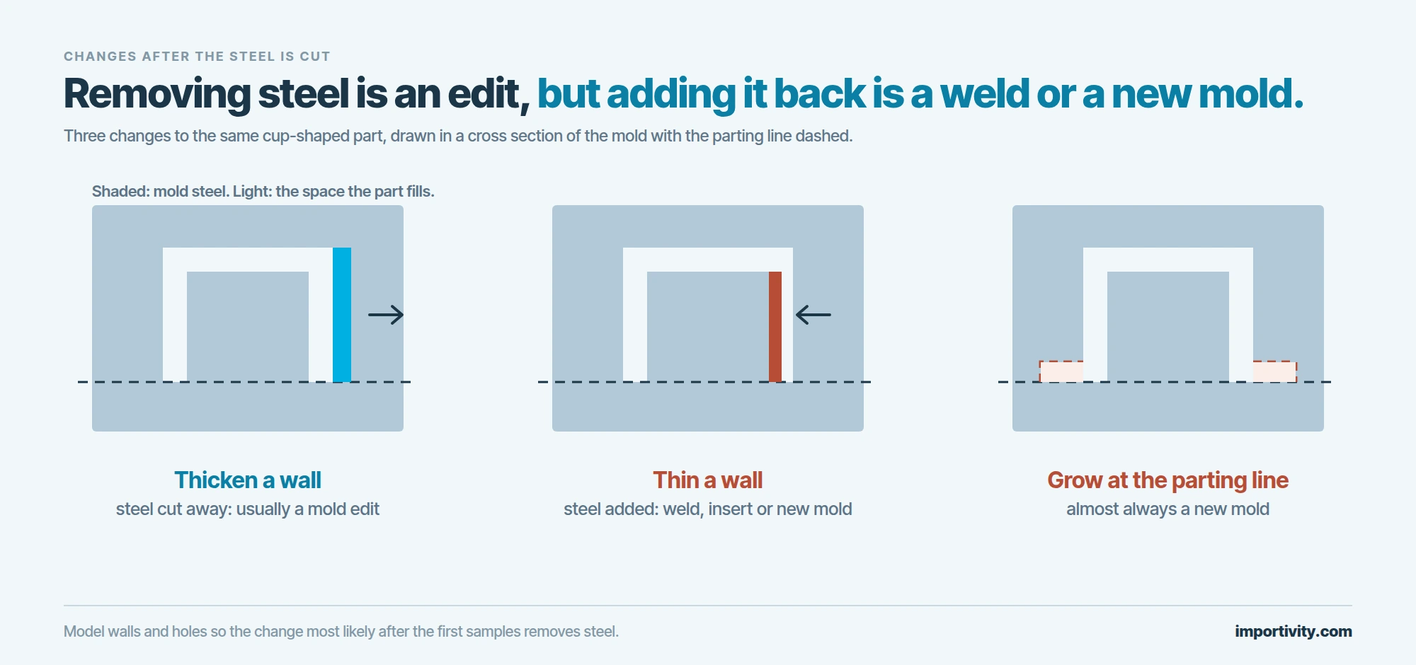
This is why toolmakers design steel safe: if a wall or a hole might change after the first samples, model it so the likely change removes steel. Protolabs advises starting voids larger and solid features such as ribs and gussets smaller, then adding plastic once testing shows where it is needed. It also notes that growing a part at the parting line will almost always need a new mold, because it changes the gating and venting.
| Change after the steel is cut | What happens to the mold | Usual result |
|---|---|---|
| Thicken a wall | Steel is cut away from the cavity | Usually a modification to the existing mold |
| Thin a wall | Steel has to be added back into the cavity | A weld, a new insert or a new mold |
| Add a rib or boss | A new pocket is cut into the steel | Usually a modification to the existing mold |
| Remove a rib, boss or text | The pocket in the steel has to be filled | A weld, a new insert or a new mold |
| Enlarge a hole or add one | The pin that forms the hole has to grow or be added | A new pin or insert, or a new mold |
| Grow the part at the parting line | The split between the two halves moves | Almost always a new mold |
A mold change also costs time. The tool comes out of the press, gets machined or welded, shoots new samples, and every feature the change touched needs a new first article check. Parts already made to the old revision may be scrap. Our guide to the pre-production sample process covers the sign-off that should close this loop before mass production starts.
Taking a product from prototype to a production tool is the work our rapid prototyping team does for US brands, and the DFM report is the document to settle before the tooling deposit leaves your account.
Frequently Asked Questions
What is design for manufacturing?
Design for manufacturing (DFM) is shaping a part so the chosen process can make it consistently at the planned cost. For a molded part that means draft on faces parallel to the mold opening, walls within the resin's range and close to uniform, as few undercuts as possible, and tolerances the process can hold. It is checked in a DFM review before tooling is ordered.
What is included in a DFM report?
A factory DFM report is usually a slide deck with draft and wall thickness maps, the parting line and gate location, the sliders and lifters, the ejector pin layout, venting and cooling, and a page of suggested changes. A full report after the tooling order adds mold flow results such as weld lines, air traps, sink marks and warp. Answer every page in writing.
How much draft does an injection molded part need?
Protolabs recommends at least 0.5 degrees on vertical faces and 2 degrees in most situations. Textured faces need more: at least 3 degrees for a light bead blast finish (PM-T1) and 5 degrees for a medium one (PM-T2). Decide the finish of each face before the DFM review, because the finish sets the draft.
When should a DFM review happen?
After your last prototype and before you place the tooling order. A first pass usually comes with or soon after the quote, and a full report follows the tooling order with the gate location, the ejector layout and mold flow results. Approve the final report on your latest CAD revision before any steel is cut.
Can an injection mold be changed after it is made?
Often, if the change removes steel, such as thickening a wall, adding a rib or shrinking a hole. Changes that need steel added back, such as thinning a wall, removing a rib or enlarging a hole, mean welding, a new insert or a new mold. Growing a part at the parting line almost always needs a new mold.
About the author
Jordan Lewis
Chief Operating Officer, Importivity
Runs Importivity's sourcing operations across China, Vietnam, Mexico and India, from supplier negotiation through landed delivery.
Press and media inquiries: press@importivity.com